


An introduction to Hydraulic

Hydraulic systems are found in a huge variety of
applications and environments from small assembly
machinery or security gates through to piling rigs,
theme park rides, supersonic aircraft and the
bascules on London’s Tower Bridge.
Tower
Bridge BasculesWhen it was built, Tower Bridge was
the largest and most sophisticated bascule bridge
ever completed (“bascule” comes from the French for
“see-saw”). These bascules were operated by
hydraulics, using steam to power the enormous
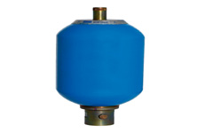
pumping engines. The energy created was stored in
six massive accumulators, as soon as power was
required to lift the Bridge, it was always readily
available. The accumulators fed the driving engines,
which drove the bascules up and down. Despite the
complexity of the system, the bascules only took
about a minute to raise to their maximum angle of 86
degrees.
Today, the bascules are still
operated by hydraulic power, but since 1976 they
have been driven by oil and electricity rather than
steam.
The use of hydraulics enables the
operator to achieve significant work (lifting heavy
loads, turning a shaft, drilling precision holes,
etc.) with minimum effort through the application of
Pascal’s Law, which states that the: “Pressure
applied to any part of a confined fluid transmits to
every other part with no loss. The pressure acts
with equal force on all equal areas of the confining
walls and perpendicular to the walls.” Because
hydraulic fluid is nearly incompressible, it is able
to transmit power instantaneously.
In
addition to hydraulic fluid, the main components
that make up a hydraulic system are the reservoir,
pump, valve(s) and the actuators, (the motor,
cylinder etc.) Looking at each of these in turn:
Reservoir: The reservoir holds a volume of
hydraulic fluid and allows any solid contaminants to
settle at the bottom of the reservoir while
transferring heat from the system, and helping air
and moisture to be released from the fluid.
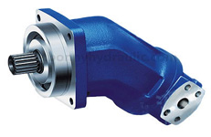
Pump: The hydraulic pump converts mechanical energy
into hydraulic energy by moving, or transmitting,
the hydraulic fluid. There are several types of
hydraulic pumps including gear, vane and piston (see
our Hydraulic Pumps page in our Technical Library
for more information). In all cases, the role of the
hydraulic pump is to displace fluid volume against a
resistant load or pressure.
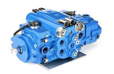
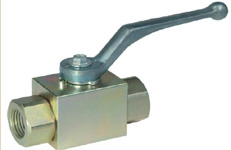
Valves: Hydraulic
valves are used to start, stop and direct the flow
of hydraulic fluid in the system.
Actuators:
Hydraulic actuators come at the end of the process,
where the hydraulic energy is converted back to
mechanical energy. This can be done through using a
hydraulic cylinder which converts hydraulic energy
into linear motion and work, or a hydraulic motor
which converts hydraulic energy into rotary motion
and work.
If you are looking for more general
information on hydraulics then we have more for you
within our reference and hydraulic products pages.
The following articles may be of interest too:
How hydraulic cylinders work
The hydraulic cylinder consists of a cylinder
barrel, in which a piston connected to a piston rod
moves back and forth. The barrel is closed on each
end by the cylinder bottom (also called the cap end)
and by the cylinder head where the piston rod comes
out of the cylinder. The piston has sliding rings
and seals. The piston divides the inside of the
cylinder in two chambers, the bottom chamber (cap
end) and the piston rod side chamber (rod end). The
hydraulic pressure acts on the piston to do linear
work and motion.
Flanges, trunnions, and/or
clevisses are mounted to the cylinder body. The
piston rod also has mounting attachments to connect
the hydraulic cylinder to the object or machine
component that it is pushing.
A hydraulic
cylinder is the actuator or “motor” side of the
system. The “generator” side of the hydraulic system
is the hydraulic pump which brings in a fixed or
regulated flow of oil to the bottom side of the
hydraulic cylinder, to move the piston rod upwards.
The piston pushes the hydraulic oil in the other
chamber back to the reservoir. If we assume that the
oil pressure in the piston rod chamber is
approximately zero, the force on the piston rod
equals the pressure in the hydraulic cylinder times
the piston area (F=PA).
The piston moves
downwards if oil is pumped into the piston rod side
chamber and the hydraulic oil from the piston area
flows back to the reservoir without pressure. The
pressure in the piston rod area chamber is (Pull
Force) / (piston area – piston rod area).
A hydraulic cylinder (hydraulic actuator,
hydraulic ram) consists of the following parts:
Cylinder Barrel: The cylinder barrel is mostly a
seamless thick walled forged pipe that must be
machined internally. The cylinder barrel is ground
and/or honed internally.
Cylinder Bottom or
Cap: In most hydraulic cylinders, the barrel and the
bottom are welded together. This can damage the
inside of the barrel if done poorly. Therefore some
hydraulic cylinder designs have a screwed or flanged
connection from the cylinder end cap to the barrel
(see “Tie Rod Cylinders” below). In this type the
cylinder barrel can be disassembled and repaired in
future.
Cylinder Head: The cylinder head is
sometimes connected to the barrel with a sort of a
simple lock (for simple cylinders). In general
however, the connection is screwed or flanged.
Flange connections are the best, but also the most
expensive. A flange has to be welded to the pipe
before machining. The advantage is that the
connection is bolted and always simple to remove.
For larger hydraulic cylinder sizes, the
disconnection of a screw with a diameter of 300 to
600 mm is a huge problem as well as the alignment
during mounting.
Piston: The piston is a
short, cylinder-shaped metal component that
separates the two sides of the cylinder barrel
internally. The piston is usually machined with
grooves to fit elastomeric or metal seals. These
seals are often O-rings, U-cups or cast iron rings.
They prevent the pressurized hydraulic oil from
passing by the piston to the chamber on the opposite
side. This difference in pressure between the two
sides of the piston causes the cylinder to extend
and retract. Piston seals vary in design and
material according to the pressure and temperature
requirements that the hydraulic cylinder will see in
service. Generally speaking, elastomeric seals made
from nitrile rubber or other materials are best in
lower temperature environments while seals made of
Viton are better for higher temperatures. The best
seals for high temperature are cast iron piston
rings.
Piston Rod: The piston rod is
typically a hard, chrome-plated piece of cold-rolled
steel which attaches to the piston and extends from
the cylinder through the rod-end head. In double
rod-end hydraulic cylinders, the actuator has a rod
extending from both sides of the piston and out both
ends of the barrel. The piston rod connects the
hydraulic actuator to the machine component doing
the work. This connection can be in the form of a
machine thread or a mounting attachment such as a
rod-clevis or rod-eye. These mounting attachments
can be threaded or welded to the piston rod or,
sometimes, they are a machined part of the rod-end.
Rod Gland: The hydraulic cylinder head is fitted
with seals to prevent the pressurized hydraulic oil
from leaking past the interface between the rod and
the head. This area is called the rod gland. It
often has another seal called a rod wiper which
prevents contaminants from entering the hydraulic
cylinder when the extended rod retracts back into
the cylinder. The rod gland also has a rod bearing.
This bearing supports the weight of the piston rod
and guides it as it passes back and forth through
the rod gland. In some cases, especially in small
hydraulic cylinders, the rod gland and the rod
bearing are made from a single integral machined
part.
A hydraulic cylinder should be used for
pushing and pulling only. No bending moments or side
loads should be transmitted to the piston rod or the
cylinder. For this reason, the ideal connection of a
hydraulic cylinder is a single clevis with a
spherical ball bearing. This allows the hydraulic
actuator to move and allow for any misalignment
between the actuator and the load it is pushing.
Hydraulic motor technology
A hydraulic motor (or hydraulic actuator) is used to
convert the kinetic or potential energy (hydraulic
pressure and flow) of a fluid (hydraulic oil) into
mechanical energy and rotation, the hydraulic motor
being the rotary counterpart to the hydraulic
cylinder.
Hydraulic motors, hydraulic pumps
and hydraulic cylinders can be combined together
into hydraulic drive systems. When one or more
hydraulic pump is coupled to one or more hydraulic
motor, a hydraulic transmission is then created with
hydraulic fluid being used under pressure to drive
machinery.
The useful power in any hydraulic
drive system is calculated as a product of flow and
pressure, minus any inefficiencies. Therefore, when
selecting a hydraulic motor and/or hydraulic pump
for a specific application the relationships between
flow, displacement, speed, torque and pressure, and
the influence of any inefficiencies must be taken
into account.
Hydraulic motors have many
applications including: winches and crane drives,
wheel motors for military vehicles, self-driven
cranes, excavators, conveyor and feeder drives,
mixer and agitator drives, roll mills, drum drives
for digesters and kilns, shredders for cars, tyres,
cable and general recycling, drilling rigs and
trench cutters.